Metamaterial S parameter extraction

This page describes how to calculate the meta-material S parameters of a metamaterial device.
Understanding S parameters
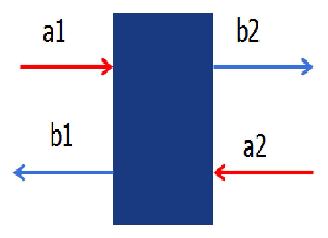
S parameters describe behaviors of a 2 by 2 network or transmission lines (see the figure below):

S parameters for a 2 port network
for two given input signals a1a1 and a2a2, the outputs b1b1 and b2b2 can be calculated as
(b1b2)=(S11S12S21S22)(a1a2)(b1b2)=(S11S12S21S22)(a1a2)
Measuring S parameters from your FDTD simulation
S parameters are complex amplitude reflection and transmission coefficients (in contrast to the power reflection and transmission coefficients). For example, S11S11 is the reflection coefficient and S21S21 is the transmission coefficient for a1a1 incidence; and S22S22 is the reflection coefficient and S12S12 is the transmission coefficient for a2a2 incidence.

Phase compensation for source and monitors
Recognizing that the a,b coefficients are directly proportional to the electric fields, the S parameters can be calculated from the definition above, eg, S11=b1/a1=Er/EiS11=b1/a1=Er/Ei and S21=b2/a1=Et/EiS21=b2/a1=Et/Ei where Ei,Er,EtEi,Er,Et are the incident, reflected and transmitted electric fields. This technique makes it very simple to obtain S-parameters for a given device, but it does make a number of assumptions. It’s important to ensure that all of the assumptions are valid for your simulation.
- To measure the S parameters in the near field (as done in the S parameter analysis object), the transmitted and reflected fields must be propagating like a simple plane wave at the point of measurement. The measurements will not be correct if evanescent fields are present. To avoid the evanescent fields, make sure the monitor is sufficiently far from the structure.
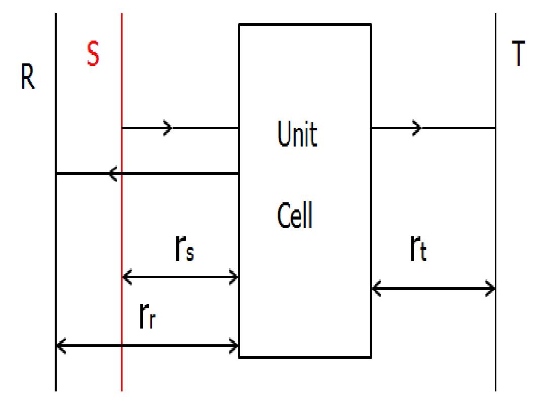
- In your simulation, the sources and monitors are always some distance from the surface of the metamaterial (for example, the monitors must be far enough from the structure to avoid evanescent fields). The fields will accumulate additional phase as they propagate from the source to the metamaterial, and from the metamaterial to the monitors. The S parameters are intended to characterize only the metamaterial, without this additional propagation phase, thus we must compensate this additional phase. Suppose the wavenumber in the incidence space is ki, and the wavenumber in transmission space is kt, the extra phase in Monitor T from source S is kirs+ktrt where rs and rt are distances (so they are positive). For reflection Monitor R, the extra phase from source S is kirs+kirr .
Based on the above discussion, a ready-to-use grating S Parameters analysis group is available in the Object Library. In most cases you only need to set the slab thickness, the locations of the slab center and source position along x axis, and the background refractive index in Analysis–Variables. The phase compensation is done in the Script. Note that because the reflected and transmitted waves must be propagating like plane waves, we use a point-type frequency-domain monitor, to record the electric field component. The analysis group also contains two 2D surface-monitors, which are used to measure the power transmission and to check that the fields are in fact propagating like a single plane wave.
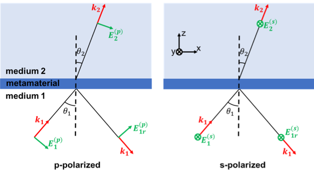
This analysis group calculates the S parameters (amplitude and phase) of a metamaterial, based on grating projections of the near-field data collected by DFT monitors for transmission and reflection. The analysis group isolates a particular output grating order, which can be selected by the user (see the analysis properties description below). The S parameters are defined so that for a planar structure they match with the Fresnel coefficients, defined according to the convention in Reference [1] (see diagram below). This convention is consistent with the behaviour of the stackrt script command. Therefore, if the media above and below the metamaterial have different refractive indices, |S12|2|S12|2 and |S21|2|S21|2 can be larger than 1. The analysis group can handle oblique incidence and s and p-polarized light for input and output.

Fig.1 Convention for s- and p-polarized light used in S parameter calculation.
This analysis group has several setup properties, which are described in detail in the setup script inside the object. Here it is worth mentioning:
- “start wavelength” and “stop wavelength”, which specify the wavelength range of the source. If the start and stop wavelength are not the same, the number of frequency points used can be set in the global monitor properties.
- “source_type”, which is used to select between two types of sources: 1 for Bloch/periodic and 2 for BFAST. Only use “source_type” = 2 for broadband simulations at oblique incidence (see Source – BFAST). In the present example, we will consider normal incidence only and so we set “source_type” = 1.
In addition, it is important to set the following analysis properties (for more information refer to the information in the analysis script of “s_params_adv”):
- “metamaterial center” and “metamaterial span” specify the region that you consider to be the metamaterial in global coordinates. This information is used to subtract an additional phase to the S parameters due to the location of the source and the hemisphere where the far-field is calculated. This is similar to the phase correction procedure described here.
- “target_grating_order_out” specifies the particular output grating order that will be considered to calculate the S parameters.
- “suppress_warnings” disables (suppress_warnings = 1) or enables (supress_warnings = 0) pop-up windows with warning messages (see description below). If warnings are generated, the “warnings” result will be 1.
Warnings will be generated if:
- The polarization of the source is not either S or P.
- The desired order was not found for some of the frequency points. This will happen when the target grating order is not supported.
The analysis group generates two S-parameter results: “S” and “S_polarization”. The first one is the S parameter for dominant input polarization and the same output polarization (e.g. if the source is s-polarized, it will calculate the result only for the s-polarized transmitted and reflected light). The second one is the S parameter for dominant input polarization and both output polarizations, which is only useful when we expect the polarization to be rotated by the metamaterial. In the simple case considered here, there is no polarization rotation and so we can simply use the “S” result and its attributes: “S11_Gn” and “S21_Gn” (source in medium 1) and “S22_Gn” and “S12_Gn” (source in medium 2).
Related publications
- D. R. Smith et al., “Electromagnetic parameter retrieval from inhomogeneous metamaterials”, Phys Rev E 71, 036617 (2005)
- Szabó, Z., G.-H. Park, R. Hedge, and E.-P. Li, “A unique extraction of metamaterial parameters based on Kramers-Kronig relationship,” IEEE MTT, vol. 58, no. 10, 2010, pp. 2646-2653
- P. Yeh, “Optical Waves in Layered Media”, Wiley-InterScience, chap. 3, 2005.