How I set up my personal domain on my NAS

A walkthrough starting with buying a domain, publishing a website on a Synology NAS and having a cool email address

János SzuroveczJan 6, 2020·8 min read

I was thinking a lot what title I should give to this post as I am going to cover a bunch of things here. I intentionally did not mention any technology or service provider in the title as you can tailor it for your own needs: you may not have a Synology but a QNAP NAS or you may rather prefer Google G Suite over Zoho Mail.

I would like to show you how I set up my NAS to reach that via HTTPS, how I run my website there, how I managed to create a firstname@surename.com email address, which looks really professional in a CV. I am also sharing with you some best practices and explanations why I decided to use the following technology stack:

  • Synology DSM 6.2
  • Any DNS provider
  • Cloudflare
  • Let’s Encrypt
  • Zoho mail

Buy your custom domain

First you will need a custom domain name. I decided to use szurovecz.hubecause Szurovecz is my surename and I wanted a cool email address built from my name: janos[at]szurovecz[dot]hu. I also wanted to publish my website on janos.szurovecz.hu. Needless to say this also allows me to let my family members have their own email address and website. If [surename].com (built from your family name)is already registered then try to choose another TLD: [surename].dev or [surename].eu may still be available. Of course you can pick any available domain name you want.

I recommend you GoDaddy, Namecheap, Porkbun or Rackhost but there are thousands of DNS providers on the market. It is worth to check the price, you might be surprised about the differences.

Hey, my ISP does not give me a static IP address. What should I do?

You can pay extra money for a static IP address. It would definitely simplify your life as you will only need to edit a DNS record and you can leave that as is forever. If you do not want to pay for it or your ISP cannot provide you a static IP address then you can workaround this with Cloudflare.

What we need from Cloudflare is the ability to modify a DNS record via an API. The idea is that a background process will be checking your IP address and whenever that changes, it updates the DNS record. It is important to understand that your website may be temporarily not available for a short time until the IP address change is propagated. It should not take more than a few second or minutes, but it also means you should not use this approach for critical websites that must be available all the time.

I was using Dynu.com before I migrated to Cloudflare. Dynu.com also has an API but its free tier limits the number of DNS record you can manage. There is no such limitation in Cloudflare.

Set up Cloudflare

Create an account on cloudflare.com and add a new site. Type your domain name and select the free plan. After a quick scan all the existing records will be listed. Going forward you will be requested to change your name servers. It means you have to login to the administration interface of your domain registrar and replace the existing name servers to the cloudflare ones. Once you are done let’s wait for a while. If everything is fine then all DNS requests for your domain will first go to your registrar but the actual IP address resolution will be done by Cloudflare.

All of my DNS records

My advice is to create an A record for your NAS like nas.szurovecz.hu. Only this record will need to be updated from your NAS whenever your IP address changes. Please note that the proxy is disabled for this A record above: I do want direct access to my NAS. On the other hand the janos CNAME record is proxied, which means all requests coming to the janos.szurovecz.hu are handled by my NAS too, but users communicate only with Cloudflare not directly with my NAS. The Cloudflare proxy gives you such nice features like HTTPS, HTML compression, DDoS attack handling and last but not least it does not expose your NAS.

Update the DNS record

Docker is a great tool to run almost anything in a controlled way, in isolation on your server/workstation. In general I encourage you to check if there is a Docker-based solution when you need something. Updating the IP address in your DNS record can also be done with Docker. Moreover, Synology DSM has a nice built-in Docker integration.

Downloading a Docker image that will be updating our DNS record

Download the oznu/cloudflare-ddnsimage from the repository. Once done launch the image and click on the Advanced Settings button. You have to provide some environment variables for the image:

  • API_KEY: Here you can find how you can generate a Cloudflare key: https://github.com/oznu/docker-cloudflare-ddns#creating-a-cloudflare-api-token
  • SUBDOMAIN: The subdomain you set in the A record.
  • ZONE: The domain name you registered.
  • PROXIED: Although it is false by default, it is better to explicitly set. If you are updating a proxied record with this approach and you forget this variable then the proxy will be turned off after the first run and your origin IP will be revealed.
Important environment variables to reach the Cloudflare API

After this you can finish the wizard and your new container should be running. The log tab on the container details screen shows whether the domain update was successful.

The NAS domain now should be resolved to the current IP address.

Create a certificate for your NAS

Cloudflare gives you HTTPS support off the shelf but only if the record is proxied. As I wanted to reach my NAS directly, I had to take care off a valid certificate.

Let’s Encrypt gives you valid, trusted certificate for free. However the certificate need to be renewed every 90 days. There are plenty of ways doing this, fortunately DSM has built-in support.

In order to be able to create or renew your certificate, port 80 must be available on your NAS. If your NAS is behind a router then create a port forward in your router or define your NAS as a DMZ. You can find more information about these in your router’s manual. Actually this is one reason why this record cannot be proxied in Cloudflare.

Creating a Let’s Encrypt certificate

Create a new Let’s Encrypt certificate. Use your NAS domain name and any of your email addresses.

If the certificate is created then you can define which certificate you would like to use for which services.

Configuring the certificates

Publish your website

I really cannot explain in this post how a website can be created. You can host a static website or you can even run a dynamic one. But you have to decide the address of your site: it can be either a subdomain or the root domain. Create a CNAME record in Cloudflare and set your NAS’ domain as target. As you can see above, this record is proxied so I can utilize all those features that are provided by Cloudflare.

For a static website I recommend to use the DSM Web Station: create a new virtual host, set you document root that contains the index.html and you are done. For a more complex site you can use the power of Docker. In this case I suppose you have a running web-server in your container that need to be exposed so make that accessible from the internet.

Expose your Docker web-container

If you have a running Docker container in which there is a running web-server then you need to create a reverse proxy in DSM. You do not need to support HTTPS in your container as

  1. Your new reverse proxy could also support HTTPS
  2. Cloudflare also acts as a reverse proxy, so HTTPS support is only need to be enabled there
Creating a reverse proxy to expose our web-server running in a container

This setup allows HTTP requests coming from the internet to the janos.szurovecz.hu host and port 80 to reach the container on port 5180. As this subdomain is proxied in Cloudflare, only Cloudflare will reach this endpoint directly.

This way you can easily publish separated websites for your family members.

And finally the email

Hosting a mail server requires high availability, otherwise the incoming emails will be lost when your server is down. Therefore I chose a paid service instead of managing it on my own server. Of course I wanted to keep the cost low so I decided to use Zoho.

I used to use Google G Suite too. That is a really nice service though more expensive than Zoho. The yearly price for 1 user is only €12 in Zoho. For the same price I would go with Google but I am okay with Zoho.

Register an account in Zoho choosing Business Email.Personal email would result a name@zoho.com address. In the Control Panel you can manage your domain, but it will be asked during the sign-up process. You will need to create records in Cloudflare to prove you ownership and to reduce the risk of being recognized as a spammer. Check my Cloudflare screenshot above.

Good to know that you can create any alias, so you can use nickname@yourdomain.com too for free. You can even register multiple domains and use as alias, you will need to pay only on user basis.

This is like Lego bricks: you have to decide what you would like to achieve and check what you already have in your box. If you do not need a certificate then you can completely ignore that part. If you are using any Linux OS on your NAS then I am sure you will find how you can install Docker or how you can create a reverse proxy in Nginx running on your host. Even if you chose another email service provider quite similar steps will need to be taken.

Quite a few people need exactly the same things and having exactly the same infrastructure but if you understand the steps above, you are ready to customize it. So what is your plan now?

Update: If you would like to use a custom domain name for Photo Station and fixing the /photo path issue then read my related story: https://medium.com/@szjani/custom-domain-for-photo-station-on-a-synology-nas-c80deddb2d1b
企鹅论文 一键下载

由于Sci-Hub网址经常变动和失效,导致科研工作者不得不经常去寻找可用Sci-Hub域名,企鹅论文集成了Sci-Hub及其他免费文献下载网站,将文献下载成功概率提高数倍,只需要输入文献的DOI,即可免费一键下载95%的SCI文献!
企鹅论文创建于2019年10月,已经稳定运行1年半了,网址为doi.qqsci.com,如果记不住的话,可以加入收藏夹,或者直接百度搜索“企鹅论文

https://doi.qqsci.com/

How to Calculate a Capacitance Matrix in COMSOL Multiphysics®

Capacitance calculations in the COMSOL Multiphysics® software seem easy. If you only have two conductors, the recipe is simple: Take one conductor and set it to grounded, set the other as a terminal, and compute the solution. Then, a built-in variable delivers the capacitance. But what if you have more than two conductors, like in touchscreens, transmission lines, and capacitive sensors? If standard textbook terminology has you lost, follow along with this working example of calculating a capacitance matrix.

What Is Self-Capacitance?

Capacitance is the ability of a system to store electric charge. It can be defined by the amount of charge that a body needs in order to raise its electric potential by 1 volt against a grounded reference potential. In a linear system, this is

where Q is charge, V is potential difference relative to ground, and C is the capacitance.

Before we get to multiconductor systems, remember that by definition, even a single isolated conductor has a capacitance, defined relative to a grounded spherical shell at infinity. For the case of a conducting sphere, this self-capacitance is

We can use this formula to calculate, for example, the self-capacitance of planet Earth — it is roughly 710 microfarad.

Human bodies can also be charged up, as seen here.

Hence, the human body, too, exhibits self-capacitance (also called body capacitance). Depending on posture and the surrounding area, body capacitance is in the range of 100 picofarad and can even create a tingling sensation in humans. You can, for example, easily charge up your body capacitance to several thousand volts while brushing your hair in the morning. Make sure to be well grounded before starting the day!

Comparing Mutual and Maxwell Capacitance Matrices

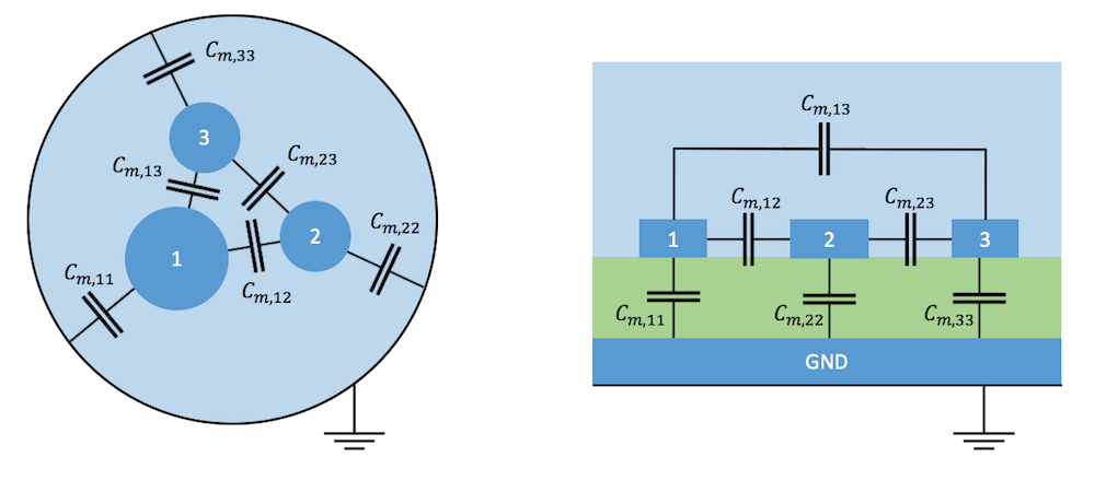
In typical electrical systems, capacitances between several conductors are of most interest. Mutual capacitance, also referred to as parasitic or stray capacitance, is desired or undesired capacitance (a buildup of charge) that occurs between two charge-holding objects. If you bring a charged object near another object, the charge distribution on the first object will change due to the process of electrostatic induction (not to be confused with electromagnetic induction). Particularly in transmission systems, capacitive coupling between lines is often unintended and troublesome, as it can create noise.

Two schematics of mutual capacitance examples.


Typical examples of mutual capacitance in a shielded three-conductor cable (left) and between microstrip transmission lines over a ground plate (right). The transition from a continuous field model to a lumped model with discrete capacitors means to shrink the conductors to points while moving the charges at their surface to the plates of capacitors shown between them.

For convenience, it is possible to arrange mutual capacitances of a system of N conductors and one additional ground in matrix form:

The coefficients of this matrix, also called partial capacitances or lumped capacitances, are used in a circuit simulator when you reduce a physical system to a network of discrete elements.

In field theory, another matrix form is more common: the Maxwell capacitance matrix. Because the name is so similar and the coefficients are not identical, it is important to understand the relation between mutual and Maxwell capacitance matrices. The Maxwell capacitance matrix describes a relation between the charge of the ith conductor to the voltages of all conductors in the system.

The Maxwell capacitance matrix coefficient  could be determined by measuring the charge on conductor 1, when only the potential  and all other electrodes are grounded. Therefore, the matrix is also often called the ground capacitance matrix. Its inverse, , is referred to as the elastance matrix.

We can also calculate the total charge on conductor 1 by summing up the contributions from the self- and mutual capacitances as follows.

For a system with N conductors, the relation between the mutual and Maxwell capacitance matrices is then

You can easily tell a Maxwell capacitance matrix by its negative nondiagonal elements.

Working Example: Mutual Capacitance of Two Spheres

Now that we have a clear definition of the terminology, let’s explore how easy it is to calculate capacitance matrices for arbitrary systems of conductors in COMSOL Multiphysics. To feel solid ground under our feet, we’ll start with a system with a known analytical solution. (Did I mention that I love analytical solutions? Actually, whenever I start a new simulation project, I try to find a simple system with an analytic solution to reproduce.)

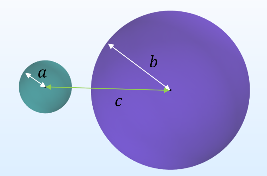
In our case, we can use a system consisting of two conducting spheres of radii a and b, separated by a distance c and a ground reference at infinity.

An illustration of two conducting spheres.


Closed-form expressions for such a system have been known since Maxwell’s times. I am referring to two readily available publications of de Queiroz (2003) and Lekner (2011). The expressions for the three Maxwell capacitance matrices are

where

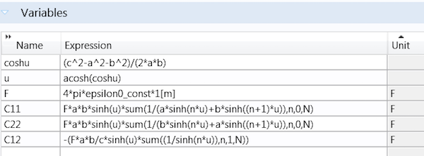
You can easily declare these expressions as variables in COMSOL Multiphysics by using the sum operator:

A screenshot showing expressions declared as variables in COMSOL Multiphysics.

With a parametric sweep over N, we find that the series converges rapidly when the spheres are not too close to each other. We can safely set N to 10 for a given set of parameters: a = 0.1, b = 0.3, and c = 0.5.

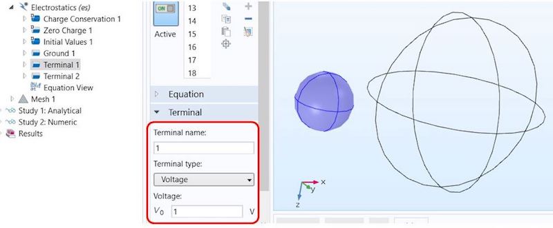
In order to calculate the capacitance matrix in the Electrostatics interface, we set a terminal condition to one sphere with a potential of 1 V.

An annotated screenshot showing the terminal condition settings in COMSOL Multiphysics.

Next, we duplicate the feature, apply it to the second sphere, and set the terminal name to 2. In order to calculate capacitance matrices, we need to apply different voltage or charge patterns to the terminals. For didactic reasons, we’ll discuss the traditional manual terminal sweep before introducing new, significantly faster technology that was released in version 5.3 of the COMSOL® software. While the new technology is faster in a large class of very common problems, the manual method is more general.

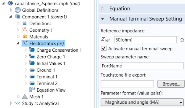
A manual terminal sweep is activated directly in the Electrostatics interface.

A screenshot showing the Electrostatics interface in COMSOL Multiphysics.

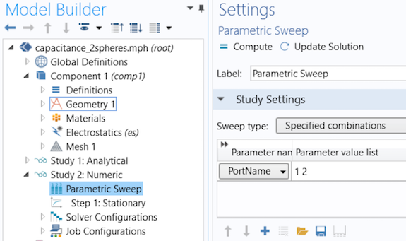
After declaring the Sweep parameter name in the Global Parameters section (PortName by default), you can then run a parametric sweep over PortName.

A screenshot with the Parametric Sweep node highlighted in the model tree.

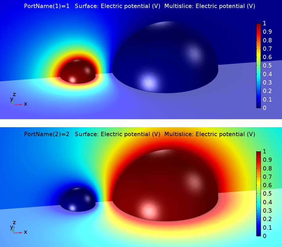
In the model, the COMSOL Multiphysics software sets one terminal to 1 V and all others to ground during the sweep, resulting in the following two solutions:

The solutions of a capacitance matrix model in COMSOL Multiphysics.

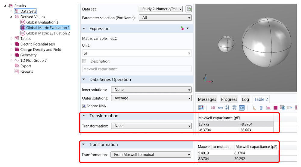
You can use Results > Global Matrix Evaluation to extract the capacitance matrices in different notations, including the Maxwell capacitance matrix and the mutual capacitance matrix.

An annotated screenshot showing the capacitance matrices in COMSOL Multiphysics.

In this simple example, their relation is

If you are setting charge terminals instead of voltage terminals, the primary solution is the inverse capacitance matrix. A set of transformations are available that can help you convert the charge into the above-mentioned matrices.

Gain Speed with Stationary Source Sweeps and the Boundary Element Method

In COMSOL Multiphysics version 5.3, we have introduced many powerful new modeling methods. One feature particularly relevant to capacitance matrix calculations is the new Stationary Source Sweep study step.

In contrast to manual terminal sweeps, which use a parametric sweep for PortName, this new technology accounts for the fact that applying different charges or voltage patterns to the electrostatic system doesn’t change the system matrix of the underlying FEM equations, only their loads. This means that the matrix needs to be inverted only once and can be reused for all other load cases. This approach can dramatically reduce computational time, especially when the number of terminals is large or other parametric sweeps (e.g., for the geometry) are needed.

Even for a moderate number of terminals, like in the Touchscreen Simulator simulation app, the speed gain is surprising: I could reach a factor of 7.8 on my machine for this model with the same number of DOF!

The new Capacitive Position Sensor tutorial model uses the Stationary Source Sweep study step.

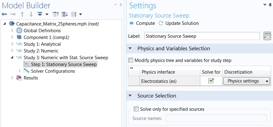
A stationary source sweep is also easier to set up. There is no need to activate a manual terminal sweep and define a PortName variable and a parametric sweep. All you need to do is select a study step. By default, the study will run through all terminals. Alternatively, you can define specified sources that you want to cover.

A screenshot of the Stationary Source Sweep settings in COMSOL Multiphysics.

If the stationary source sweep is so powerful, then why do we keep the traditional approach at all?

There are cases where we appreciate a recalculation of the system matrix; for instance, in nonlinear or multiphysics problems or if meshes should be adapted for each terminal configuration. In such cases, a manual terminal sweep is a better method.

Another powerful feature that comes with version 5.3 of the COMSOL® software is the boundary element method (BEM) in electrostatics. Compared to FEM, where a mesh in all domains (including the surrounding air domain) is needed, BEM avoids meshing in the infinite void, which reduces the number of DOFs. You can learn more about combining BEM in electrostatics and capacitance matrix calculation in the Modeling a Capacitive Position Sensor Using BEM tutorial.

Can’t wait to learn more about the new BEM implementation? Read about how this method has already helped to simplify corrosion modeling in a previous blog post.

Concluding Thoughts on Capacitance Matrix Calculation

In this blog post, we have looked into the calculation of capacitance matrices, discussed the different terminologies, and provided a numerical solution for a well-known problem that has a closed-form solution. While the simple model presented here can provide a reference for your own models, the new features released in version 5.3 can help you to create large models with many terminals and additional parametric sweeps more efficiently.CONTACT COMSOL FOR A SOFTWARE EVALUATION

Additional Resources

References

  1. de Queiroz, A.C.M., 2003, “Capacitance Calculations“.
  2. Lekner, J., 2011, “Capacitance coefficients of two spheres”, Journal of Electrostatics 69(1):11-14.

电场调控下的浮动薄膜多彩结构

https://mp.weixin.qq.com/s?__biz=MzU5NjM5Njc2Mw==&mid=2247513206&idx=1&sn=a30ab380f95b359ad7223b2f765dd9e9&chksm=fe61abc2c91622d4bd1695b8b41a8e161dcac62f2265667b0a73c807ce1c0aa6892abc1d475f&mpshare=1&&srcid=0425bBu1qLOd4Orj1RKZEElv&sharer_sharetime=1619360087995&sharer_shareid=cfcd208495d565ef66e7dff9f98764da&scene=2&subscene=1&clicktime=1619413444&enterid=1619413444#rd

电场调控下的浮动薄膜多彩结构

Original 长光所Light中心 中国光学Yesterday收录于话题#纳米光子学2#忆阻器1

Image
Image
Image
Image
Image
Image
Image

Banner | 商务推广


中国光学

中国光学中科院长春光机所Light学术出版中心旗下学术传播与服务平台,带你解读全球光学最新研究进展。442篇原创内容Official Account

说明 | 本文是由论文作者投稿
颜色,作为最直观的物理特性之一,在人类文明发展的历史长河中扮演着重要角色。《孟子・告子上》中所写,“目之于色,有同美焉”,更有《道德经》对五色的描述“五色令人目盲”。
对光和色彩的调控是一个亘古不变的问题,我们在惊叹千年前敦煌莫高窟的绚烂壁画的色彩技术时,更致力于对色彩和光的各种研究和应用。
色彩显示技术在材料科学,结构工程,物理,化学,光学和半导体等工业部门都拥有极大的关注,如仿生结构,光子晶体,等离激元,功能材料,3D 打印,全息投影显示,彩色显示器和信息安全等领域。其中,色彩调控技术是各项技术前进和突破的核心指标之一。

Image

图1 敦煌莫高窟彩色壁画
当前针对色彩调控技术的研究,主要围绕在对材料性质的调控,包括化学反应,相变转换,光敏,机械和热响应等功能材料。例如N.Liu等人基于金属等离子基元设计的超高彩色显示器,通过暴露在特殊气氛环境(H₂/O₂)下的氧化还原反应,可以实现色彩的动态调控(代表论文:Nat Commun 8, 14606 (2017).  | 原文阅读 >)。Harish等人巧妙利用相变材料构筑的薄膜结构,非晶态到晶态的转换可帮助器件实现的颜色显著改变(代表论文:Nature 511, 206–211 (2014). | 原文阅读 >)。然而,因为切换前后两种功能已经固定,原位上进行每个单元的任意切换仍然无法得到实现。总结之前的研究,固态器件的物理结构,在加工制备后通常是固定的,而物理结构是光学性能的基础。因此,如何实现固态器件物理结构的调控仍是一个颇具挑战的科学和工程问题。
针对这一个问题,Anders等科研人员在等离子体结构色领域,提出了利用激光调控固态结构的方法:激光热效应可以改变原有的固体结构单元的几何形状,从而实现颜色的改变(Nature Nanotech 11, 325–329 (2016). | 原文阅读 >)。这种技术仍依赖前期复杂的结构制备工艺,而且很难实现精准和可逆化驱动。因此,如何实现简化制备工艺和调控加工成型后固态器件的物理结构,依然是一个巨大的挑战。
薄膜结构因拥有相对简易的制备工艺和高兼容的集成特性,是大部分光学,电学,光电器件,磁性存储,太阳能等器件的基础单元。基于不同材料的多层薄膜结构所显示的光学特性,展示了丰富的颜色及其广泛的应用场景。固体薄膜器件在加工制作完成后,其物理结构通常被固定。
近期,来自新加坡科技大学的Chong Tow Chong教授,联合新加坡国立大学的仇成伟(Qiu Cheng-Wei)教授和清华大学的赵蓉(Zhao Rong)教授,提出了一种可调控的动态薄膜结构设计,能够实现在电场调控的可逆结构色。
研究成果以“Floating Solid-state Thin Films with Dynamic Structural Colour”为题,发表在NATURE NANOTECHNOLOGY上。
该项研究利用了电场下金属Ag离子的迁移活性,巧妙地设计了无序态(amorphous | 名词解释 >)氧化铁为中间介电质层的可调薄膜结构(如图2)。电场驱动下,Ag离子的迁移可以实现薄膜器件的厚度,层数和层序的改变,从而实现单一器件多种颜色的可逆调控。在反向电场下,Ag离子朝向底电极(TiW)方向移动,薄膜器件基本可以恢复到初始状态。研究人员,通过透射电子显微镜(Transmission Electron Microscope)和能量散射X射线谱(Energy-dispersive X-ray spectroscopy)元素表征(图2所示),可以确认该固态器件的物理结构实现了浮动改变。

Image

图2 动态薄膜结构设计:电场调控下的结构变化.图源:Nature Nanotechnology. (2021) Fig.1 (c)-(f)
基于这个动态薄膜的设计,研究人员使用原子力显微镜(Conductive Atomic Force Microscope | 原理解释 >)展示了这项技术应用于超高分辨率的反射型显示器的可能性。如图3,通过导电原子探针的扫描,在一个薄膜样品上,可以写出明显的彩色图形。这些彩色图形,处于non-volatile状态,无需持续的能量去维持色彩区域,这与当前的主流色彩显示技术有很大区别,可在日光下实现清晰的显示(而不需要借助外界的能量的支援)。这项技术将大大降低功耗,为实现节能环保型的新型显示器的研究提供了新的思路。图3 原子力显微镜驱动下的纳米分辨率反射型显示器展示图源:Nature Nanotechnology. (2021) Fig.3(a), (c).
随着纳米加工技术的进步,固态彩色打印技术主要是基于各种纳米等离基元结构的设计。尽管实现了超高纳米级别的分辨率,然而其耗时复杂的工艺对于宏观大尺寸的彩色打印技术,仍然是一个难题。在该项研究中,作者基于图1动态薄膜的设计,尝试了大尺寸的彩色图形的打印,图4展示了在4 inch 硅片上的彩色鱼尾狮图形和‘NUS’(National University of Singapore缩写),证明了该项研究在大尺寸固态彩色打印技术领域的可行性。图4 大尺寸彩色图形打印展示图源:Nature Nanotechnology. (2021) Fig.4(c), (d), (e).
本工作通过电场控制Ag在多层的薄膜结构的迁移,成功驱动了固态薄膜物理结构的浮动变化,进而实现单一器件的颜色大幅度的可逆调控色彩的显示无需持续的能量维持。作者基于此项设计,进一步探索了纳米级别的彩色显示器和大尺寸彩色打印的应用价值。该项研究同时为功能性光学,电学和光电等半导体相关技术的研究提供了新的窗口。
文章信息Yan, Z., Zhang, Z., Wu, W. et al. Floating solid-state thin films with dynamic structural colour. Nat. Nanotechnol. (2021). 
论文地址https://doi.org/10.1038/s41565-021-00883-7直通原文 >编辑 | 赵阳
 欢迎课题组投递成果宣传稿

转载/合作/课题组投稿,请加微信:447882024

往期推荐

Image

Light: Science & Applications | 光的“降噪”:抑制光的反向散射

Image

Nature Photonics | “机器学习”在超快光子学中的应用

Image

Science | 微型光谱仪的30年进展

新刊推荐

Image

开 放 投 稿:Light: Advanced Manufacturing

ISSN 2689-9620

期 刊 网 站:www.light-am.com

开 放 投 稿:eLight

CN 22-1427/O4   ISSN 2662-8643

期 刊 网 站:elight.springeropen.com

点这里 👇 关注我

中国光学

中国光学中科院长春光机所Light学术出版中心旗下学术传播与服务平台,带你解读全球光学最新研究进展。442篇原创内容Official Account

别忘了点赞+在看哦!喜欢此内容的人还喜欢Adv. Electron. Mater.:MXene-GaN范德华异质结,用于高速自驱动光电探测器和发光二极管Adv. Electron. Mater.:MXene-GaN范德华异质结,用于高速自驱动光电探测器和发光二极管…低维 昂维不喜欢不看的原因OK内容质量低 不看此公众号Laser Photonics Rev.:原子薄电致发光器件中的激子发射Laser Photonics Rev.:原子薄电致发光器件中的激子发射…低维 昂维不喜欢不看的原因OK内容质量低 不看此公众号Adv. Funct. Mater.:用于大面积光电探测的2D材料增强型柔性自修复光电探测器Adv. Funct. Mater.:用于大面积光电探测的2D材料增强型柔性自修复光电探测器…低维 昂维不喜欢不看的原因OK内容质量低 不看此公众号